-
Archive of July, 2013
- April 2015
- March 2015
- October 2014
- July 2014
- June 2014
- May 2014
- April 2014
- March 2014
- February 2014
- January 2014
- December 2013
- November 2013
- October 2013
- September 2013
- August 2013
- July 2013
- June 2013
- May 2013
- April 2013
- March 2013
- February 2013
- January 2013
- December 2012
- October 2012
- September 2012
- August 2012
- July 2012
- June 2012
- May 2012
Behind the fabrication
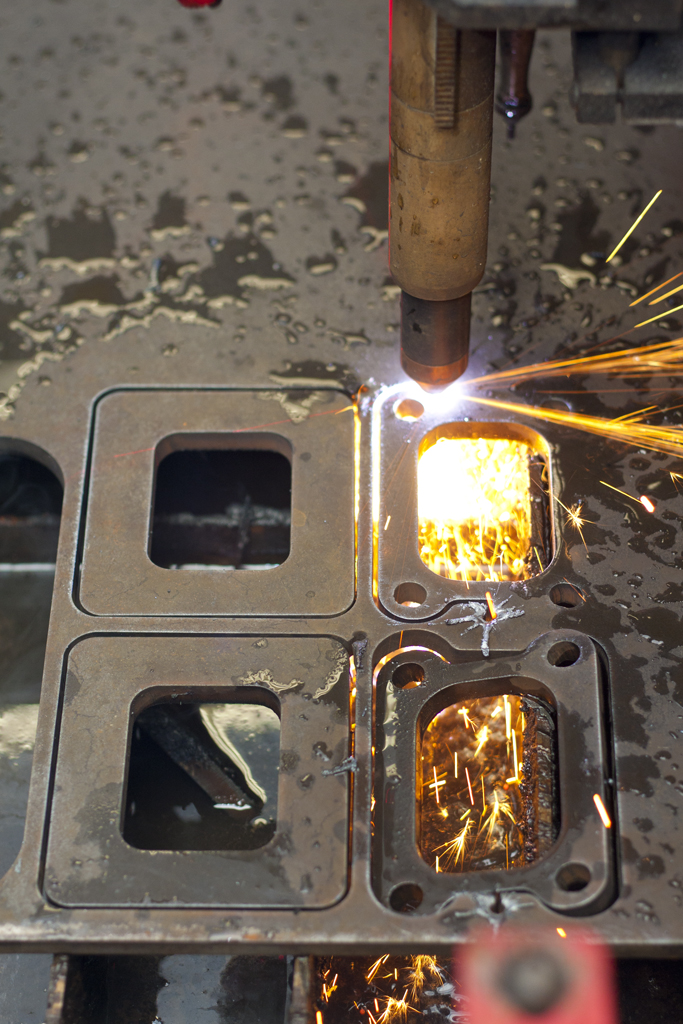
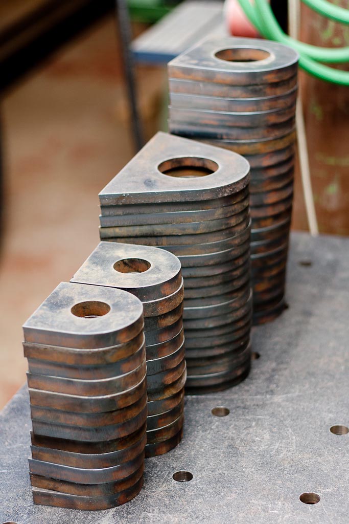
We may give off the impression that that almost all we do is fabrication. Which is not entirely true, which is why we would like to see what goes on behind the fabrication. Here’s some of the last things we’ve gone through on the CNC table. Lots of 1/2″ and 3/8″ lifting rings and turbo flanges.
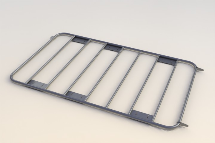
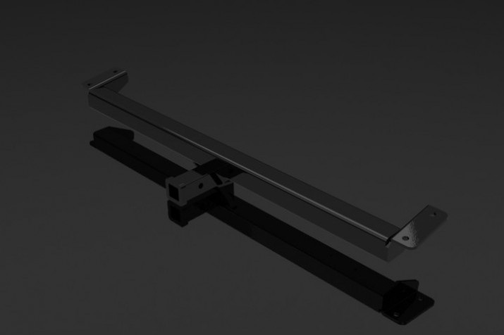
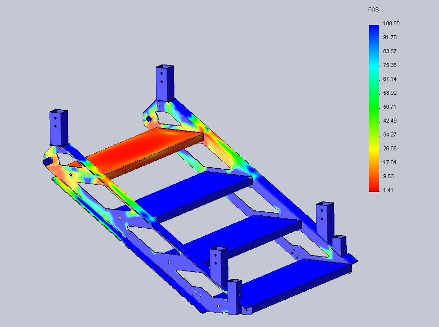
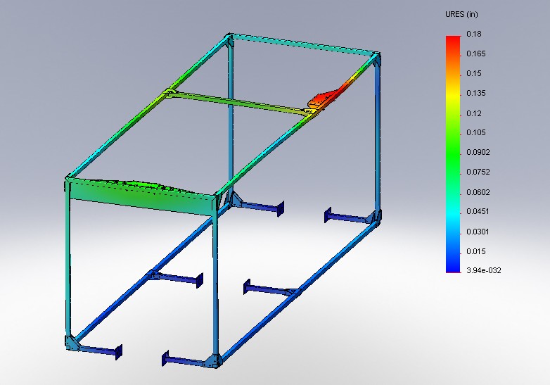
With jobs like that there is very little design work required, just nesting and setting up tool paths to cut them out as efficiently as at the highest quality possible with our table. We do a lot of mechanical design that is either “behind the scenes” once the part is fabricated, like this roof rack we will soon be building for a client.
Everything is designed to ensure that it will be easy to fabricate and the CAD files are used to produce the flanges that will be welded onto the tubing. It also allows us to determine the correct amount of material and reduce any amount of waste due to errors during the fabrication process. It’s much easier to update a CAD model than it is to re-cut and re-weld pieces. All of which waste time and money. Here’s the flanges cut awaiting the tubing to formed, cut and welded.
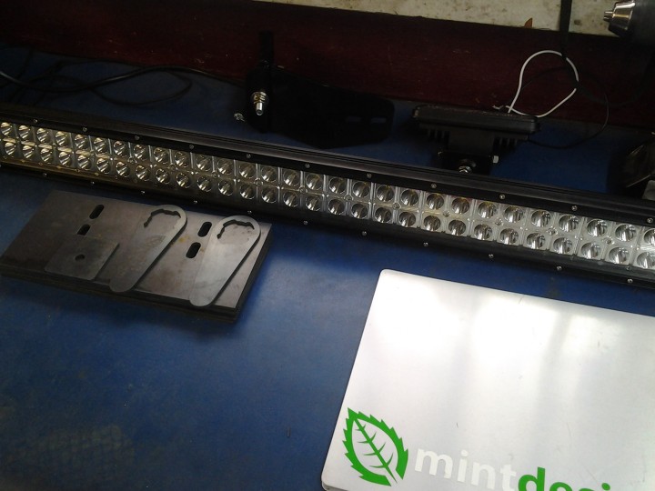
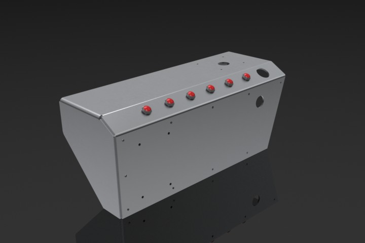
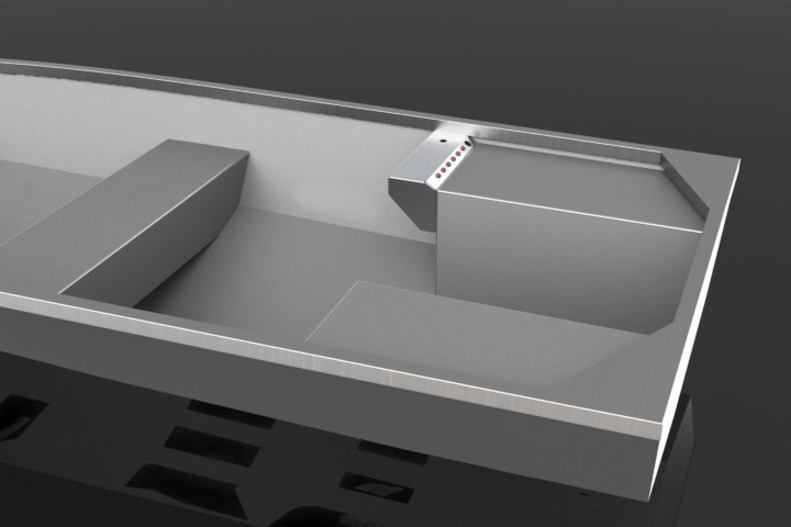
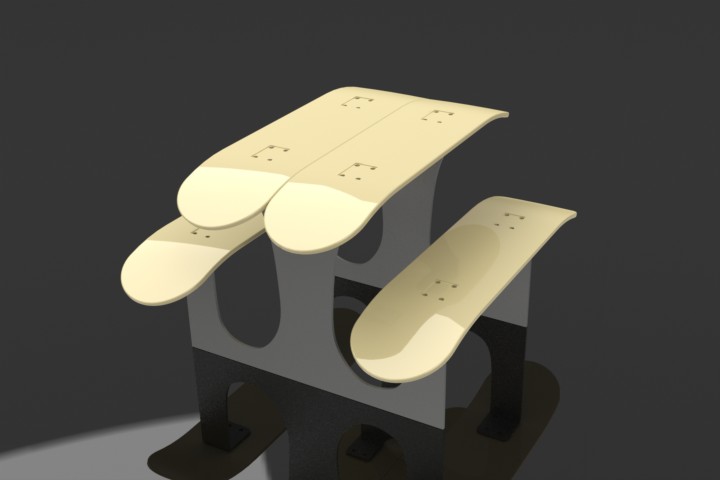
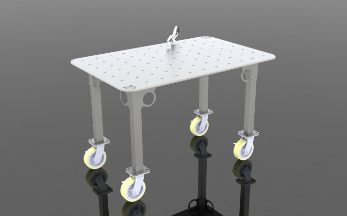
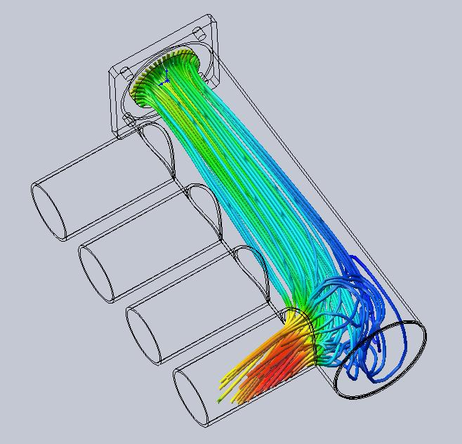
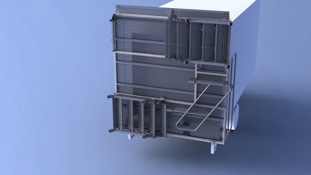
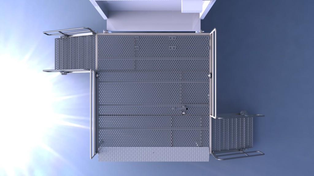
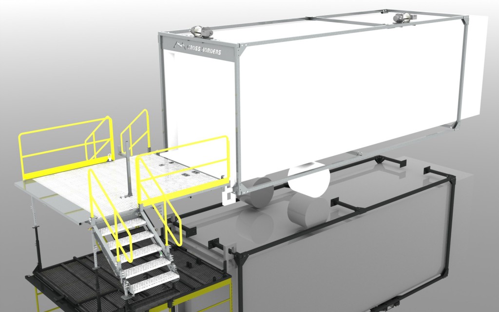
We also have many projects that are designed and sold strictly as a design, it is then left up to the customer to use those drawings and models to create what was designed. Some of these designs have NDA’s signed or have potential for a patent application so we cannot post any of these, however here are some other examples of what we’ve designed.
These are only some of the dozens and dozens of parts we have designed. Please take a look through our gallery for more images of what we’ve designed.
Ford Ranger Exhaust System
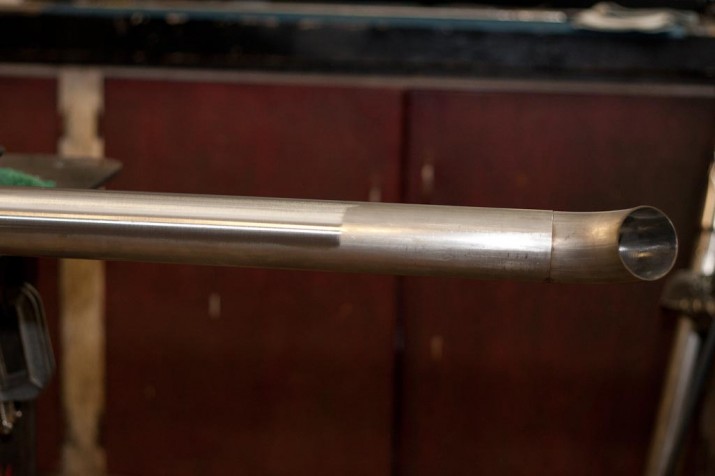
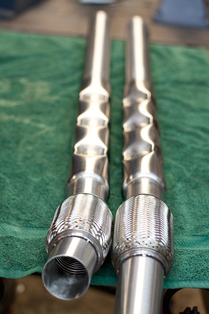
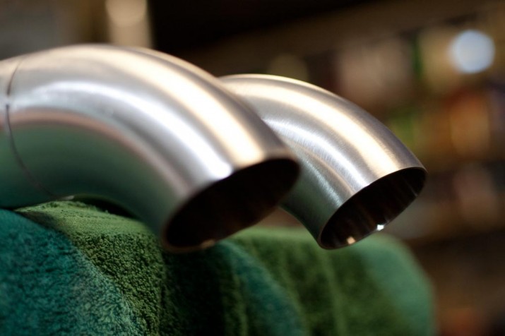
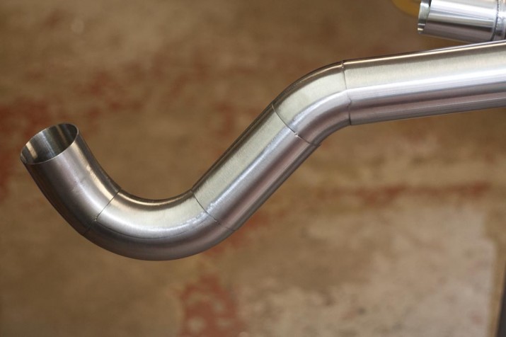
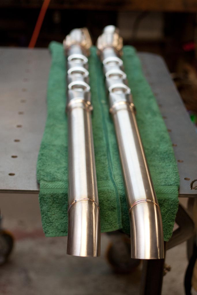
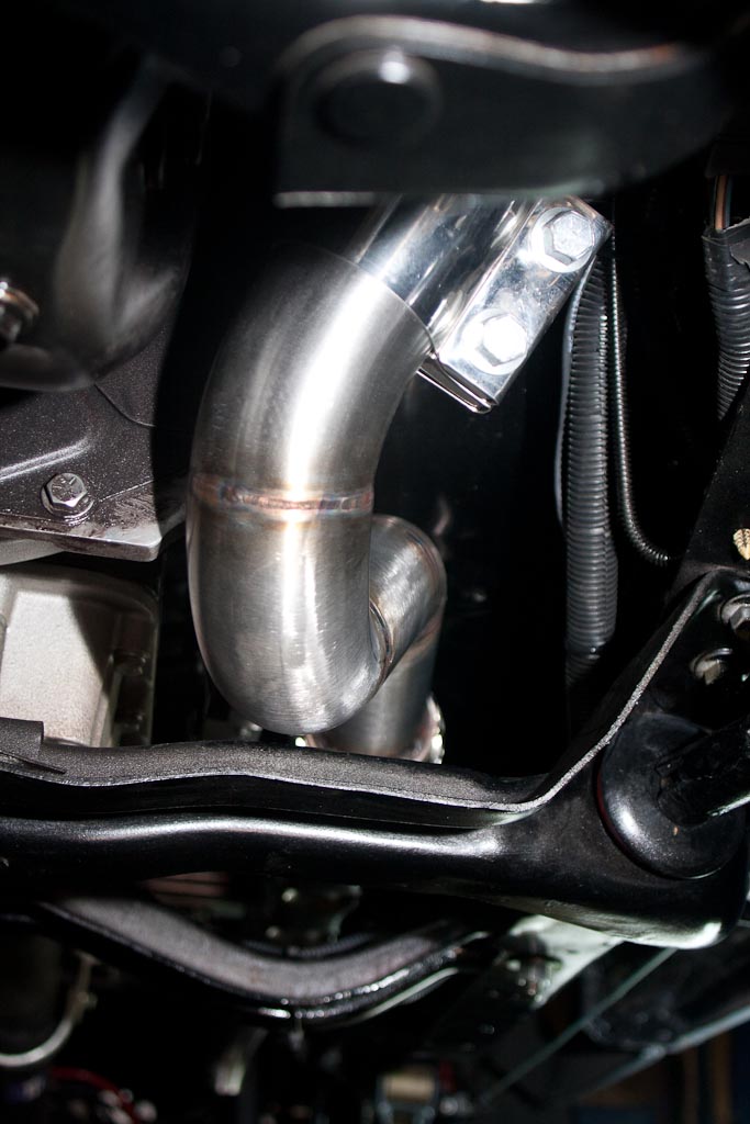
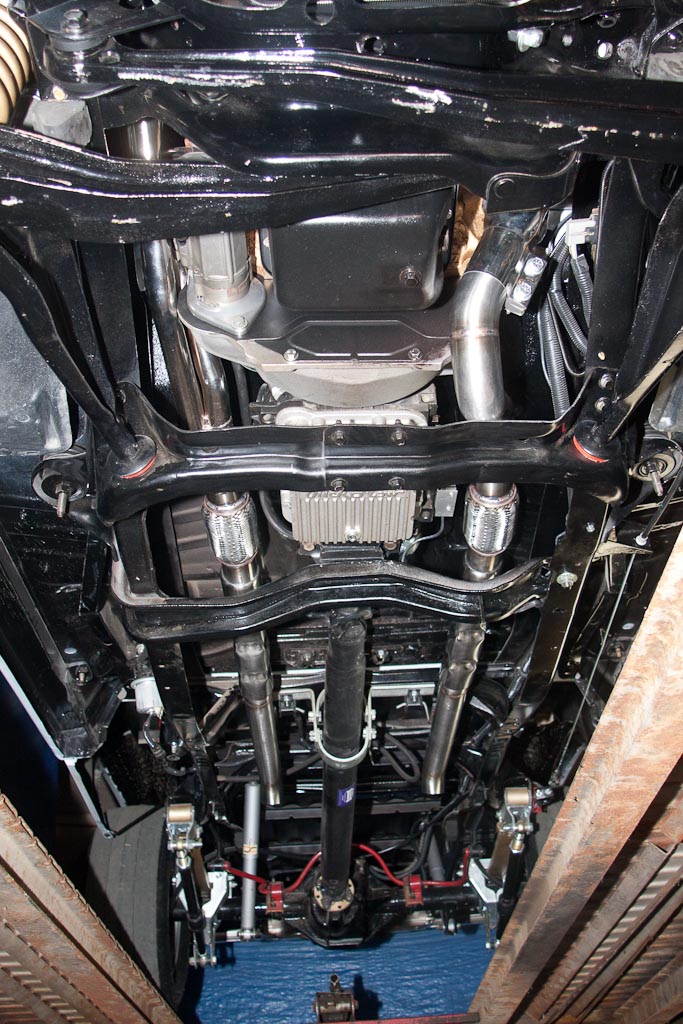
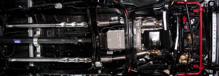
We had the pleasure of building a Ford Ranger exhaust system a little while ago. The system was all constructed from 304 stainless steel, TIG welded, backpurged and using existing holes on the frame for hanger mounts. This truck has been stripped down to the bare frame and built up with care, so this truck is as clean if not cleaner than some new vehicles we’ve worked on. The passenger side exhaust was very straightforward, but the driver’s side had an interesting header that dumped to the ground ahead of the transmission. So with the driver’s side we had to use some mandrel bends to redirect the exhaust flow around the transmission and over the sub-frame.
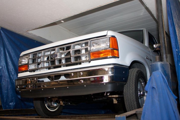
Here’s the Ford Ranger up on the hoist ready for the exhaust system to be built.
Here’s the system tacked up and ready for polishing.
Once all the tubes are tacked, then the tube polishing begins. This takes the raw 304 SS tubing and brings it to a #4 Architectural Finish, see more info here on our polishing page. Tube polishing can be done before or after welding, however most customers like the look/coloring of welds on stainless steel so we typically polish prior to welding. After polishing the tubing must be handled very carefully, wrapped, cannot sit on anything steel (due to embedding foreign material that could rust) or anything hard that could scratch the surface. Here you can see the polished on the left and raw material on the right.
And here is the polishing completed.
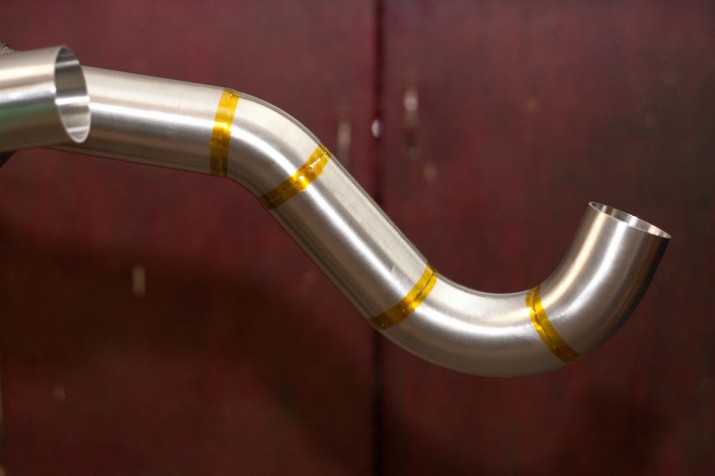
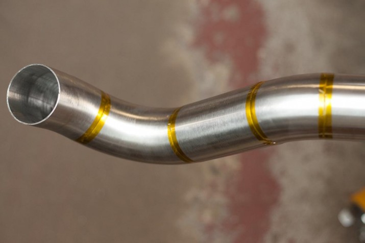
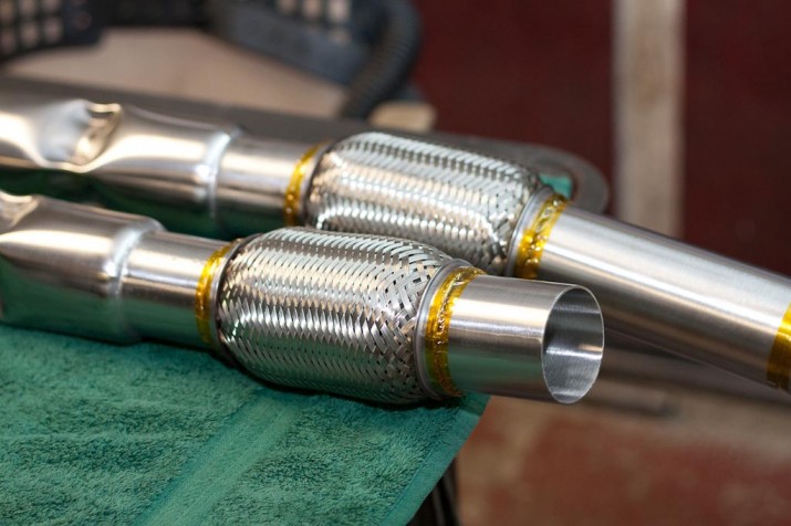
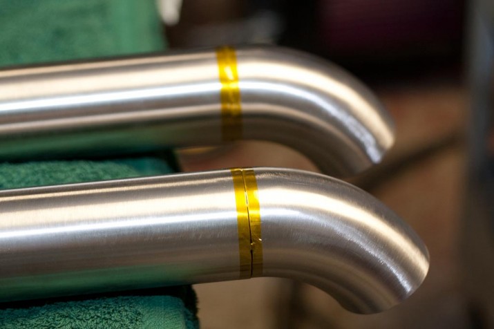
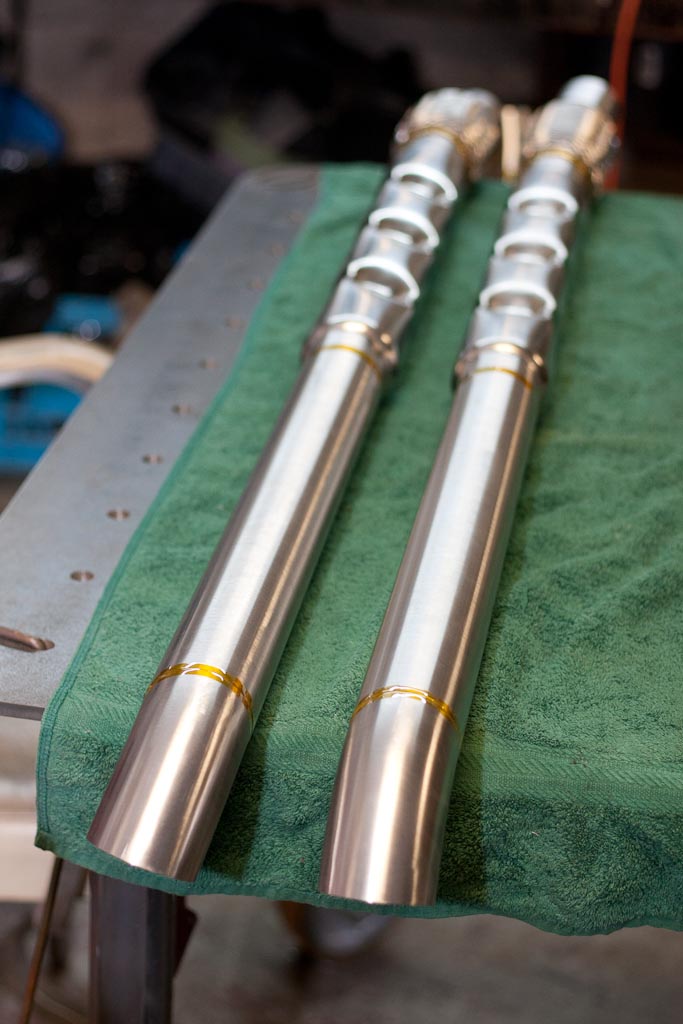
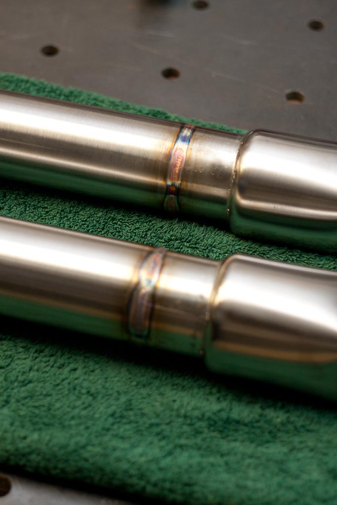
Now both tubes are tacked and polished it is time to tape all the joints and get it ready for backpurging and TIG welding. Backpurging is when the inside of the tube is filled with an inert gas, in this case Argon, this protects the backside of the weld from contamination commonly known as “sugaring”. Sugaring is an oxidized area of Chromium that combines with oxygen to form a hard thick porous oxide layer. This oxide layer depletes the Chromium content in the stainless steel near the weld and if enough is depleted the corrosion protection can be compromised. The oxide layer is porous so it leaves the inside of the weld open to corrosion and can disrupt exhaust flow. This is why backpurging is important, especially on a high quality exhaust system. Here is some prep shots prior to welding.
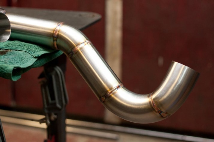
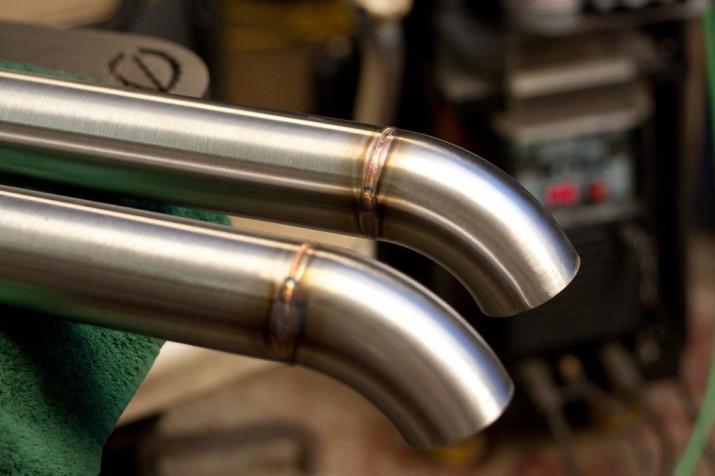
Here’s the exhaust system all welded up (sans hangers).
Now to install it on the truck. Here’s the tight hoop between the transmission and sub-frame.
If you have any questions or further interest please take a look at our Services Page or send us a message through our Contact Page. Thanks for looking.
Customer update
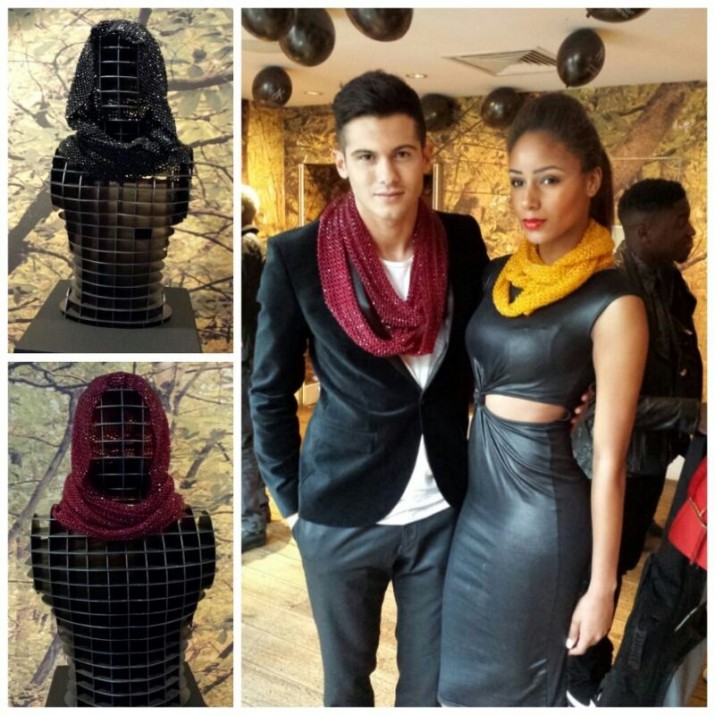
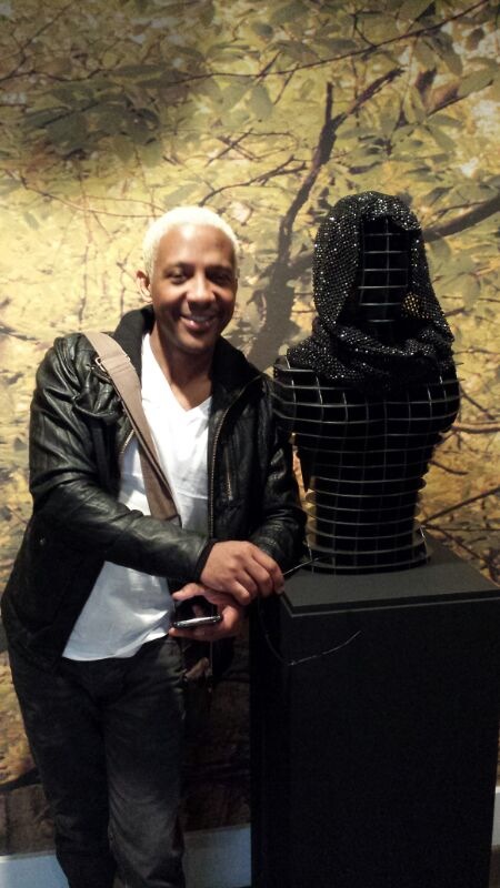
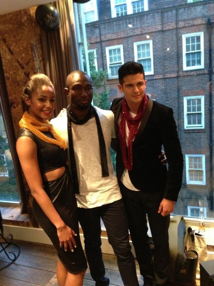
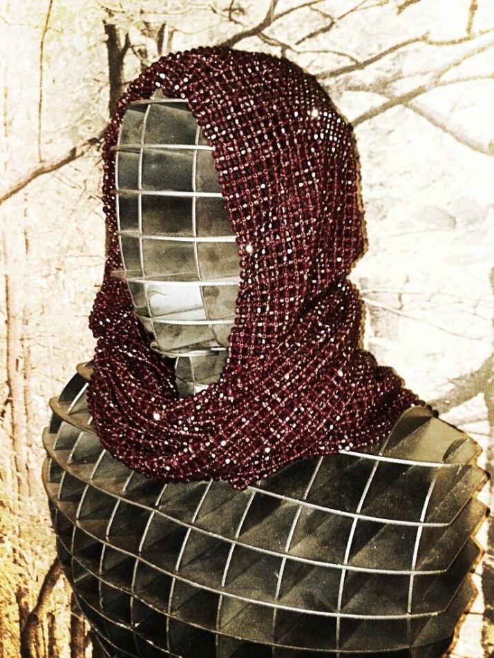
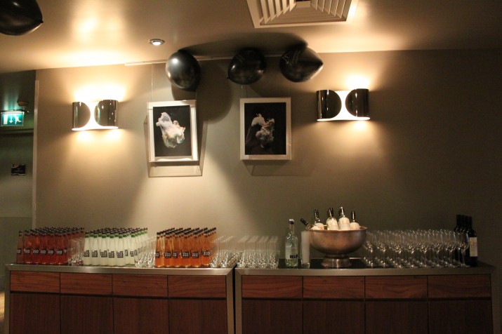
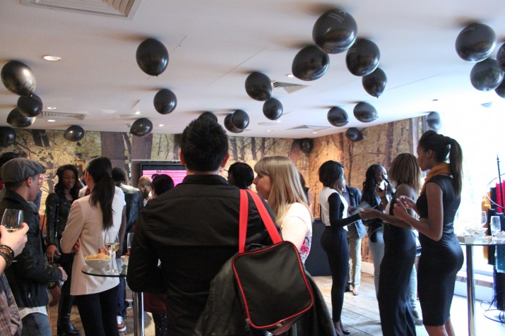
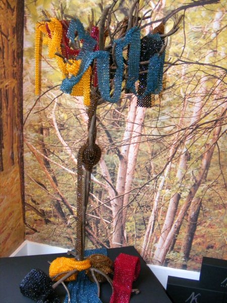
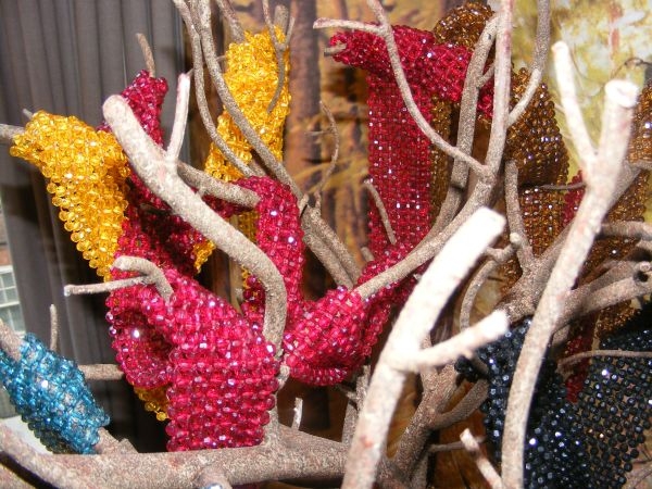
We always enjoy seeing photos of our custom products being used. So here’s a customer update. Nosakhare, a fashion designer and the owner of Nosakhari in London, UK received our mannequin packages and set them up for an expo. It seems it was a very good time and we’re glad that we could have had a small part in this show. If you haven’t read our build for these mannequins, it’s located here. We created a 3D mannequin model, sliced it into pieces and then had it cut in our in-house CNC plasma table. It was flat packed (to save on shipping costs) and assembled on site by our customer.
Enjoy the photos courtesy of Nosakhari.
DSM general modifications
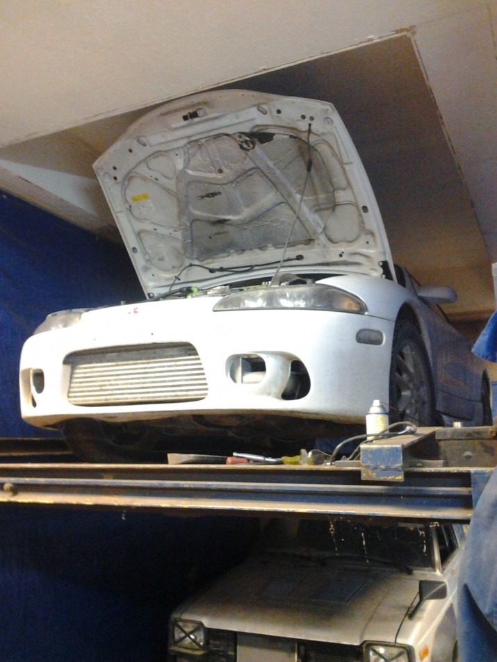
Lots of things going on in the shop lately, we just haven’t had much time to bring the camera in to take some photos. We had a DSM that needed some general modifications to get it ready for dyno tuning. We had to modify the IC piping, divorced wastegate dump as well as all the flanges for the exhaust system. Here are a few quick photos of some of the welding and work that was done. Nothing major made from scratch, but instead just ironing out any little kinks to get the car ready to really perform.
First we got the car up on the hoist and began by removing the existing exhaust system, divorced wastegate dump as well as disconnecting some of the IC piping.
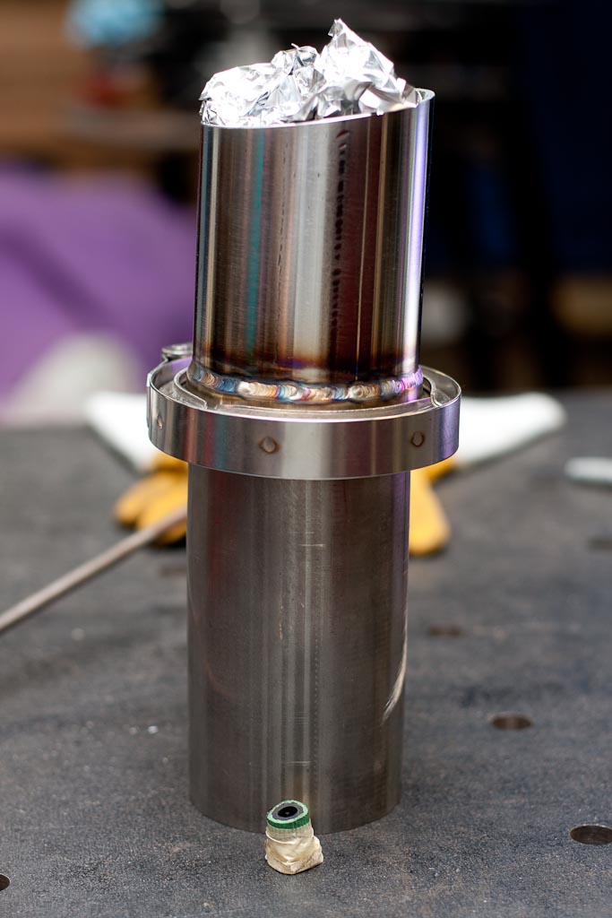
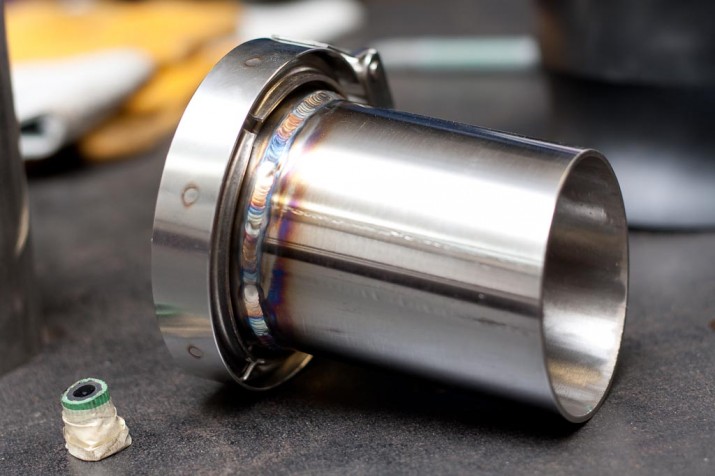
The Thermal Research and Development exhaust had all its two and three bolt flanges cut off and in their place would be a v-band clamps. Here’s one of them after being welded up. The entire tube assembly is put overtop the green hose (which is a back purge hose fed through the welding table) and the tin foil acts as a dam to keep the argon inside the cylinder while it’s being welded. There is a few small holes in the tin foil to allow argon to flow out to allow for a complete purge and ultimately an inert environment. The scrap tube on the bottom is to elevate the v-band assembly to keep it at a comfortable height during welding.
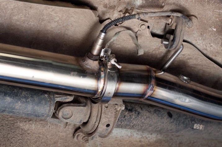
Here it is welded in place on the car.
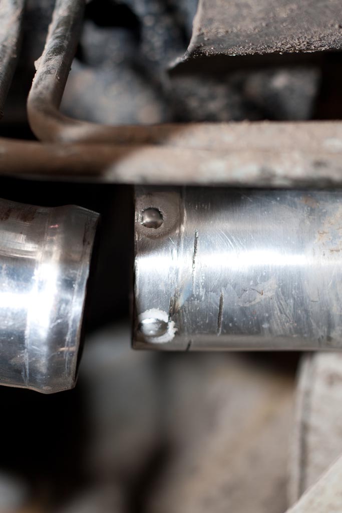
Typically to prevent a silicone coupler from coming off, either end of the tubing that butts up in the coupler must be bead rolled (as seen on the left tubing) or have weld beads applied. This “hump(s)” prevents the hose clamp from sliding and ultimately having the coupler blow off the intercooler tubing. In this case the tubing on the right is actually a part of the intercooler, which is bolted up in behind the bumper. The easiest way to retain the silicone coupler is to add a few evenly spaced beads, two of the four beads required some contortion skills. These two were the easy ones.
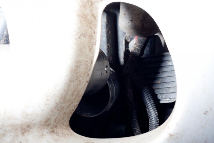
This was one of the tricky ones, the other was welded with a mirror so it was hard to get a photo. In this case one hand through a duct in the bumper with the TIG torch, and another hand coming up underneath the car with some TIG filler.
