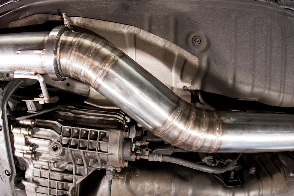
Porsche Exhaust Repair
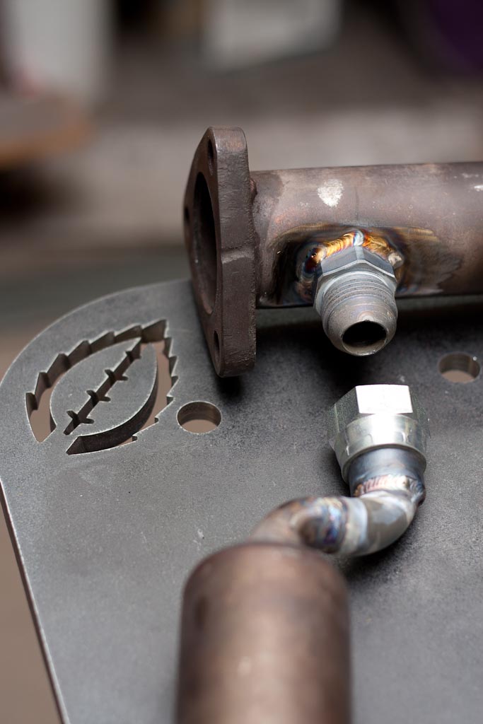
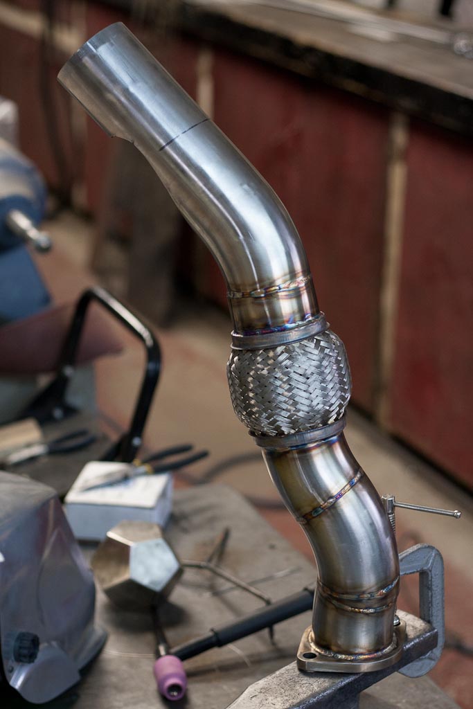
Normally we don’t do much repair work in the shop, mostly custom fabrication starting from raw materials. However having the ability to fabricate parts from scratch means there are always going to be the odd repair or retrofit of existing parts that has to be done as well. In this Porsche exhaust repair, it was repairing galled threads and some gummy welds from a previous “repair”. Overall the repair was quite simple using a angle grinder (with cut off wheel and flapper disc), plasma cutter, bandsaw and a TIG welder.
We plasma cut off the fitting on the exhaust (to the left) and cut off the entire section a bit beyond the previous welds (to avoid contaminated material). In this case we used a 3/4″ JIC fitting, one male for the exhaust and a female for the EGR. This made things very easy.
All the customer has to do is apply some Loctite Nickel Anti-Seize and this problem won’t happen again.
TIG Welding and CNC Cutting
We’ve been busy the last few days TIG welding and CNC cutting up a variety of materials and a variety of thicknesses for some local fabricators.
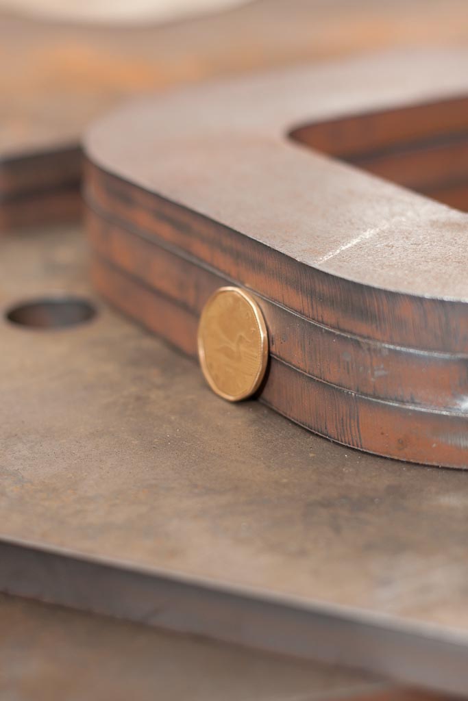
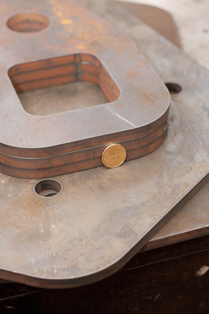
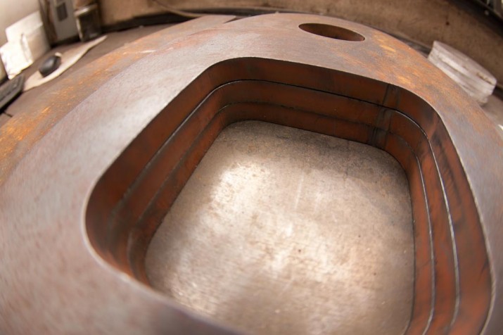
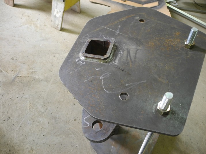
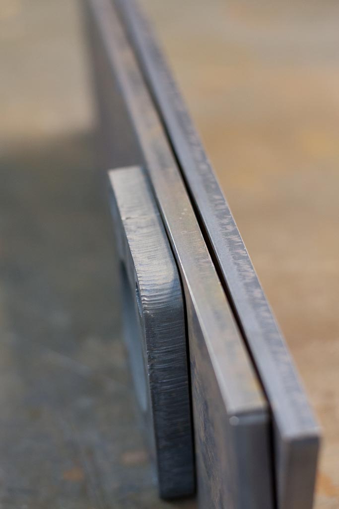
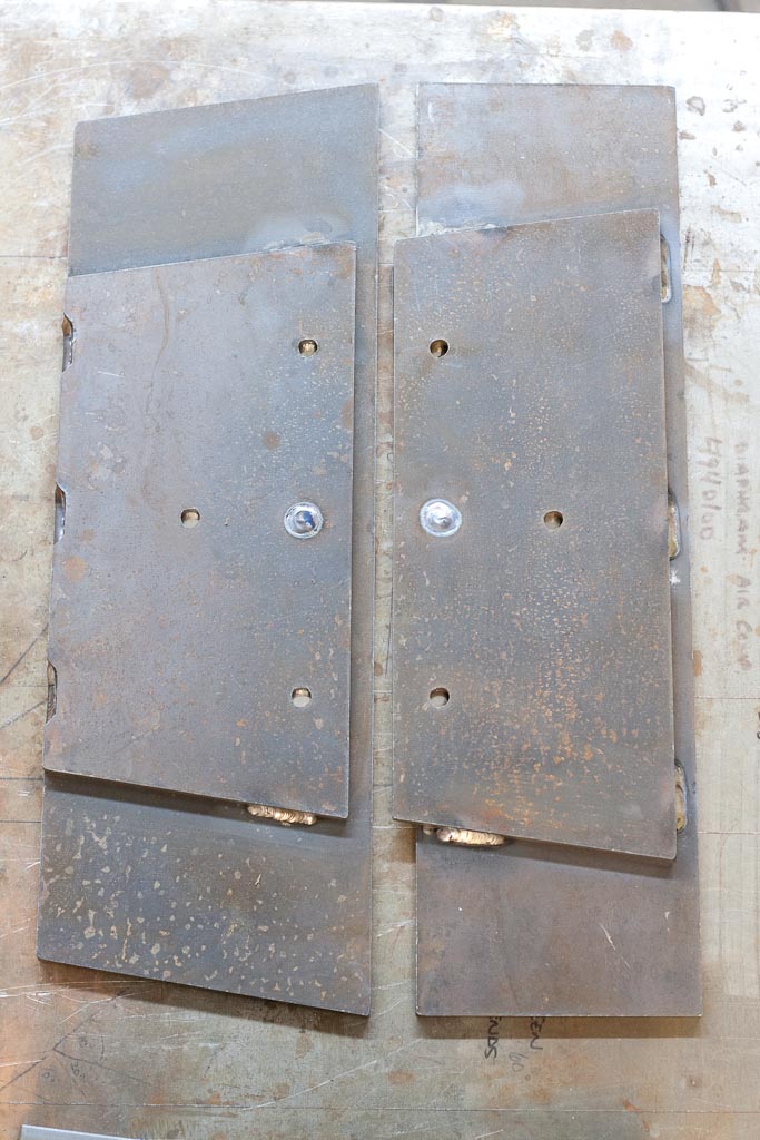
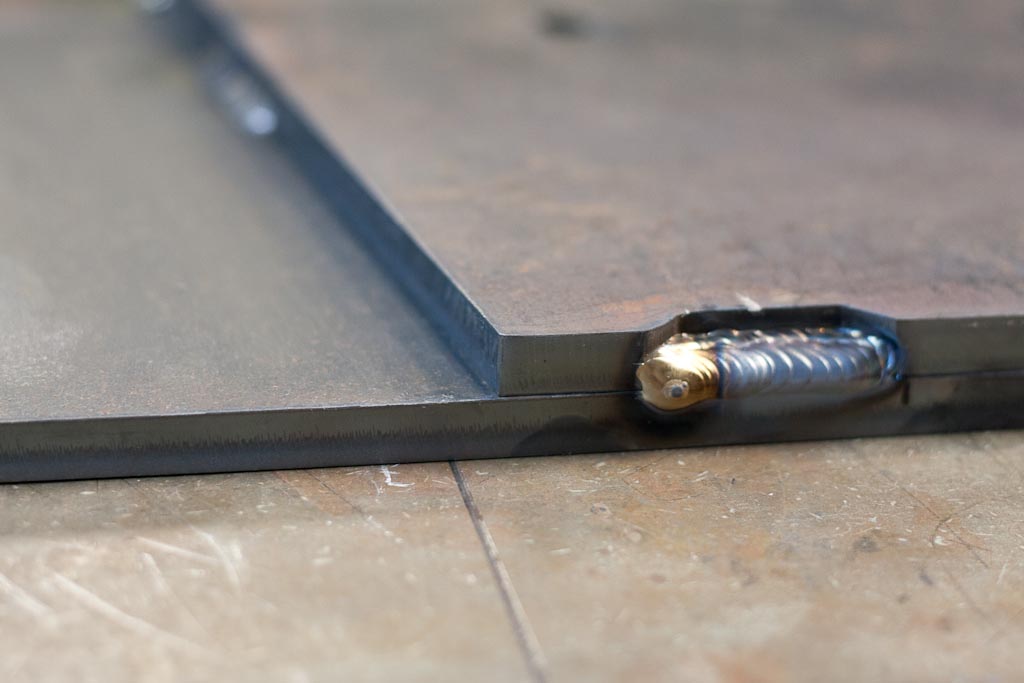
Here’s some 1/2″ 44w steel plate that we cut, the internal features were cut with the corner lockout on so it allow for a slower cutting speed and less taper. We’ve seen a huge improvement with holes!
While cutting all the half inch steel we had some room to nest a prototype rotation gauge. This tool will be used with our tubing bender to ensure that our bends are on the correct plane or what angle the plane should be. This was designed in Solidworks to be perfectly balanced left-to-right as the center of gravity is located right in the center of the “V”. It just needs a tapped hole at the bottom of the “J” for a 3/8″ bolt.
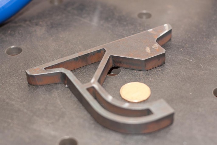
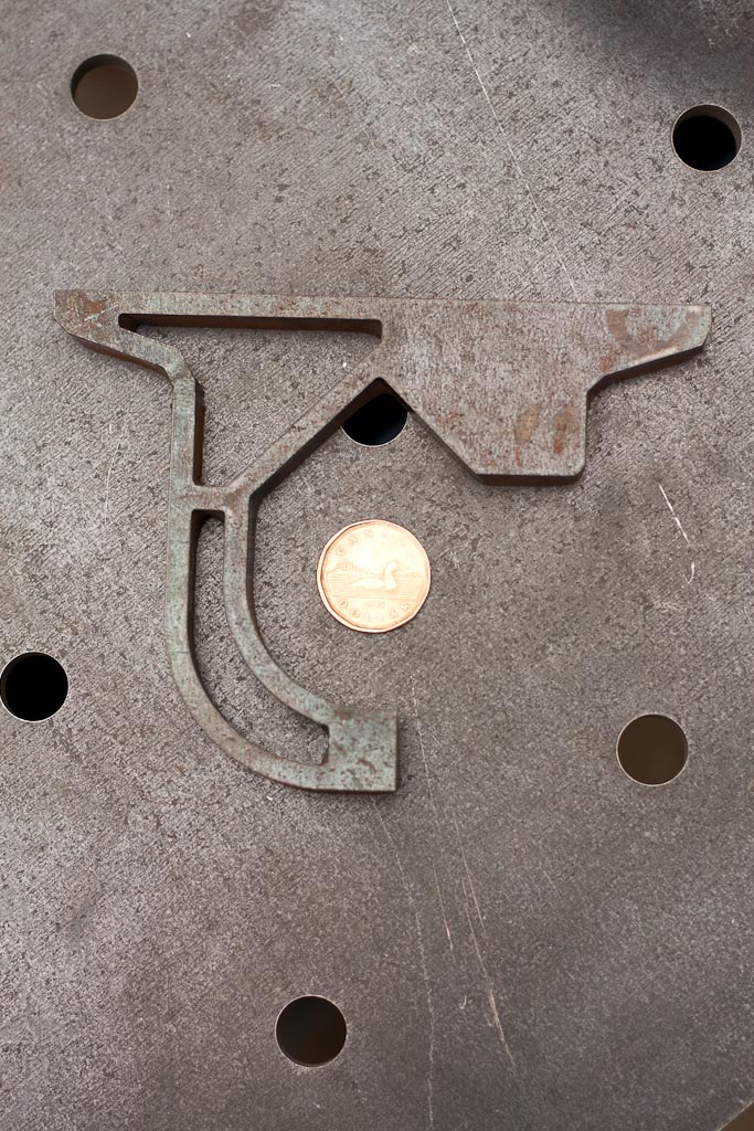
After all the heavy lifting we had a quick tweak to make with this exhaust that is destined for a Dodge Viper. The hangers were off by 1/2″ (hence the pair of black “X’s”) and needed some adjustment.
Normally we’d just cut the brackets off and just create new ones, but the customer wanted a quick fix, so instead we strategically cut the hanger, moved them to where it should be and then welded in the cuts. Made for really quick work and it provided a low cost fix.
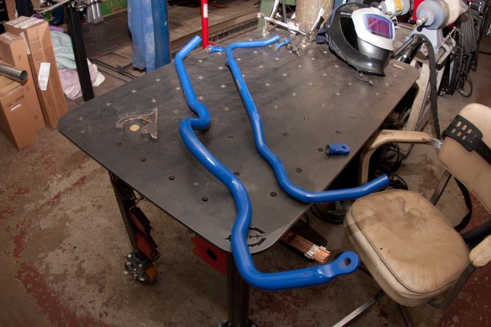
Now onto a R32 Skyline anti-sway bar modification. We already started in this photo by cutting three of the four mounting points.
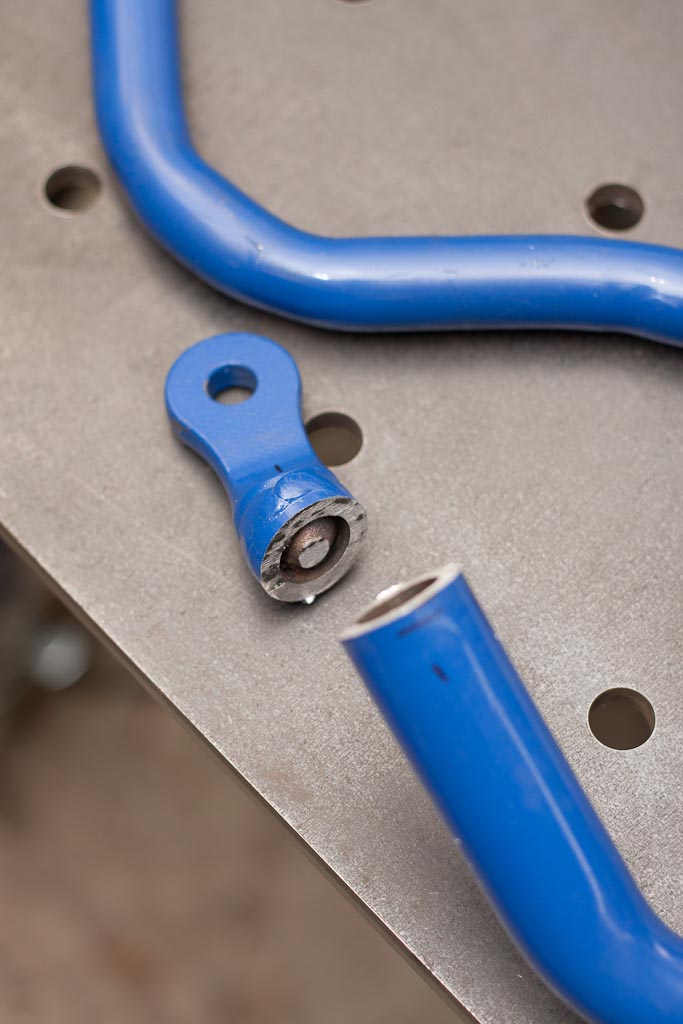
Rear anti-sway bar mount removed.
Front anti-swaybar mount removed.
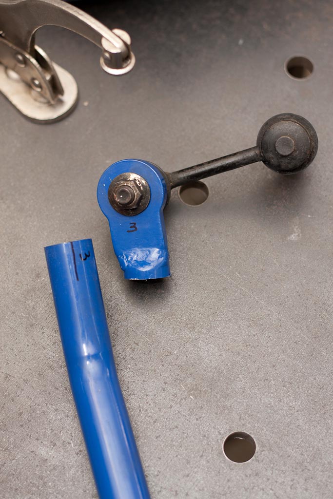
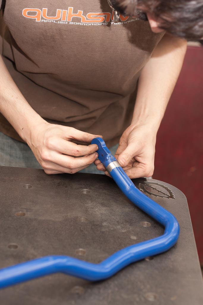
With the mounts removed the ends of the tubing are prepped. Here the removed mount is having the orientation double checked with index mark on the tube.
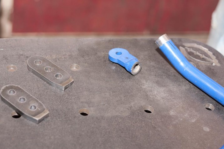
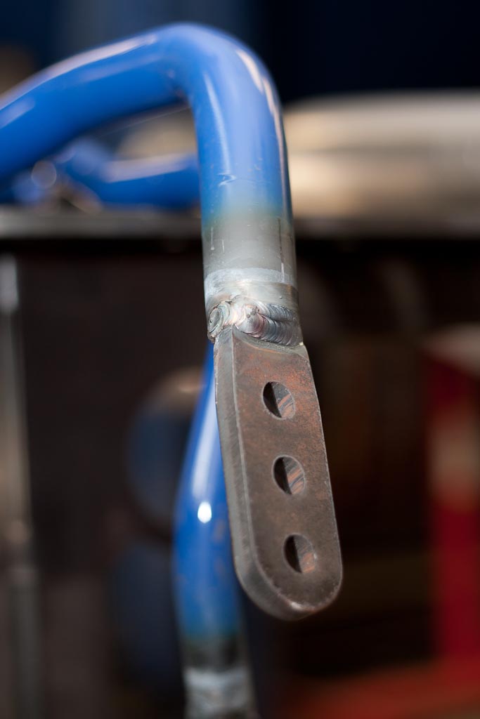
Here are the new brackets cut off the CNC plasma table. The new mount for the front allows for an additional mounting hole 0.875″ forward and behind the stock mounting location. The rear allows for 1″ forward and behind. This will allow the driver to adjust the anti-sway bar roll stiffness and alter the handling of the car.
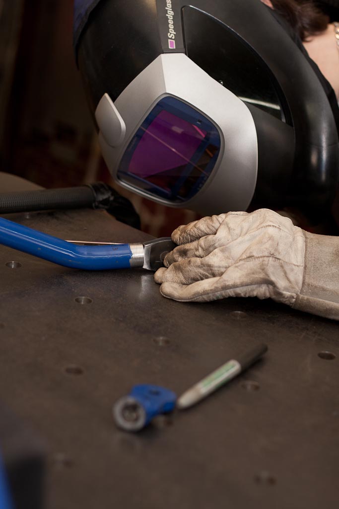
Checking alignment.
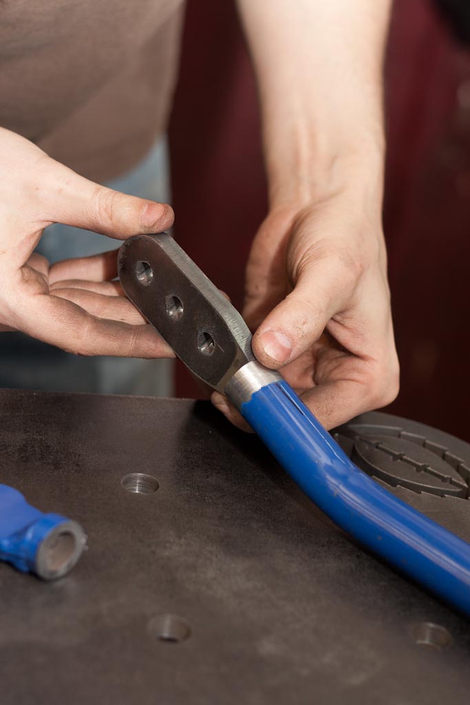
Tacking.
Checking the alignment on the other end.
Getting ready to tack.
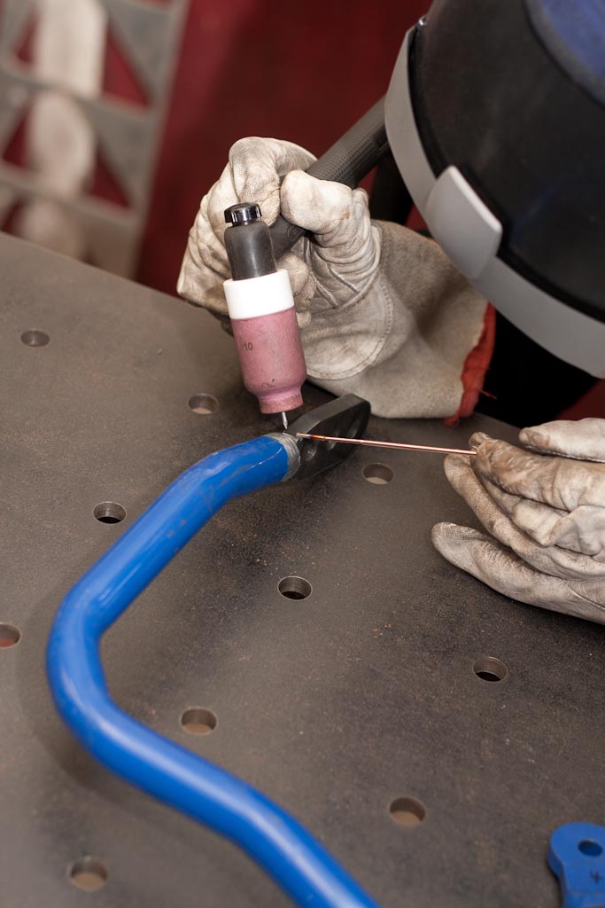
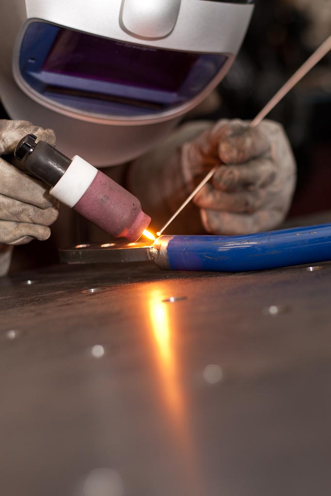
Beginning to weld them all up!
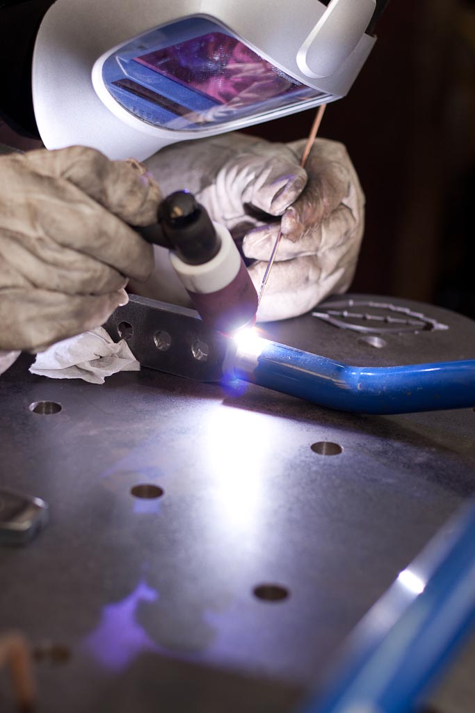
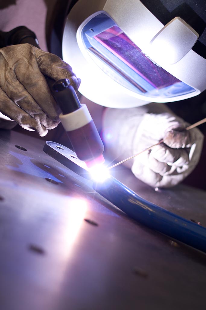
Post flow. This is when the argon is purging after the arc has been extinguished. This allows for the weld to cool down in an inert atmosphere as well as the tungsten and filler rod. This all avoids contamination and yields very high quality welds.
This was a multi-pass weld so as to ensure that this joint would be strong and not fail in this high stress area.
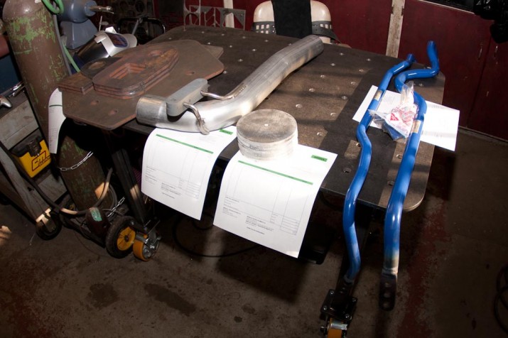
All our jobs of the day ready to pick up and go!
UPDATE – 5-May-13
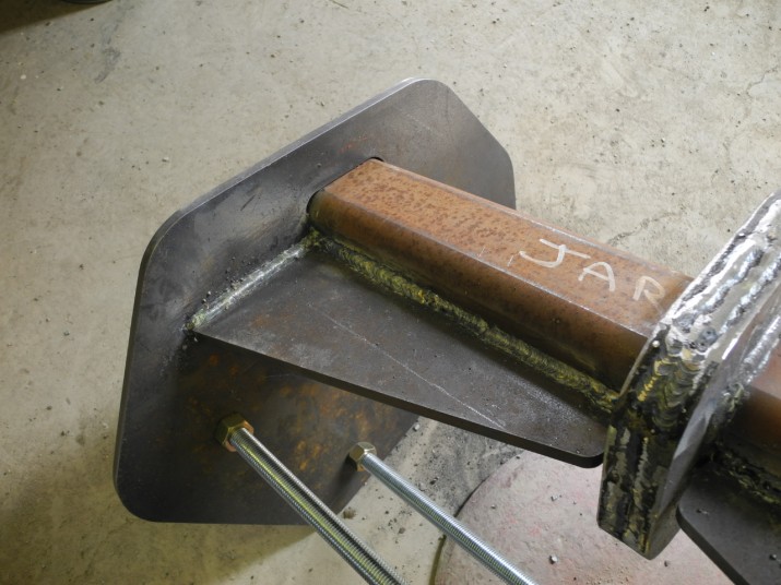
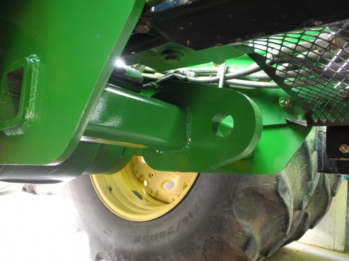
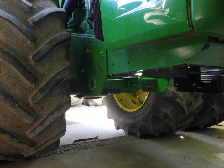
Our customer took those 1/2″ steel plates (first three photos in this post) and fabricated a hitch for a John Deere tractor.
Heat recovery plate fabrication for a fireplace
We had a customer that had a neat project, so here we are documenting a heat recovery plate fabrication project needed for a fire place. To start we’ve been busy hoisting around some 3/8″ steel in the shop to get ready to cut and weld. We also found it interesting to do a cut comparison between a local laser cutting shop and our in house CNC plasma table. The laser sample is on the left, we are very proud of the cut quality with our CNC table and this shows it. The CNC cut has a square, straight and sharp edge, while as the laser cut piece is a bit thicker (1/2″ vs 3/8″) the cut quality is very poor, pictures speak a thousand words.
This heat recovery plate setup was designed by the customer, we just cut it out and welded it. They are installed one set at a time and interlock with each other once in the fireplace.
The pieces are TIG welded together after coming off the CNC table. We pride ourselves on high cut quality, and to go along with high quality welding will always yield a very nice finished product.
Designing and building a lightbar for Toyota Rav4
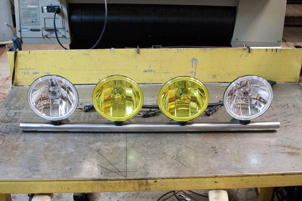
We put a lot of miles on the Mint Design Rav4, and not always in the best weather conditions. It was time for a lighting upgrade.
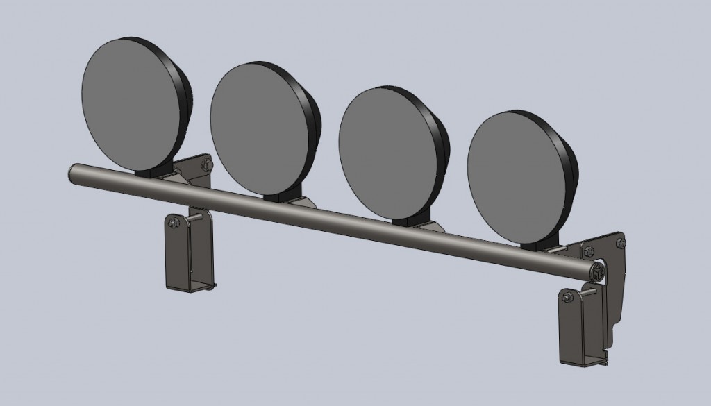
3D model.
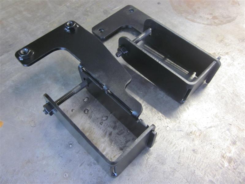
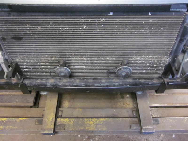
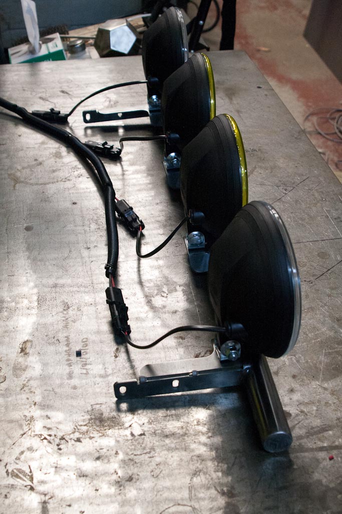
The design allows the two CNC cut plates to be linked together and then bolted to clamp onto the crash bar.
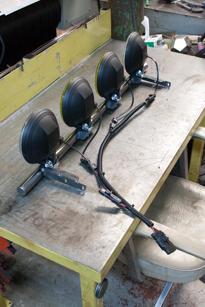
Wired up and one step closer…
And installed!
Stainless Steel midpipe section
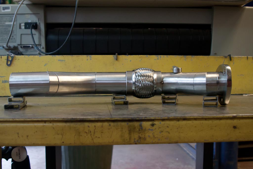
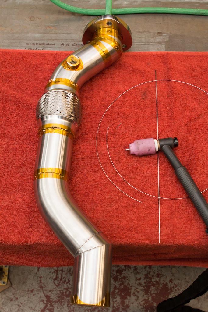
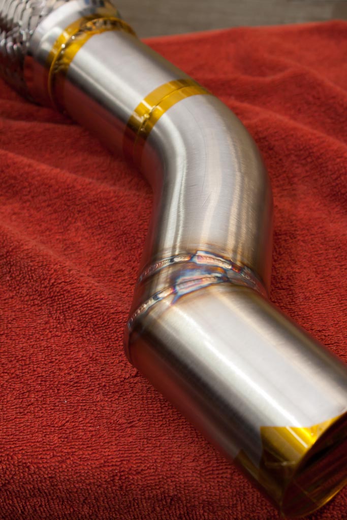
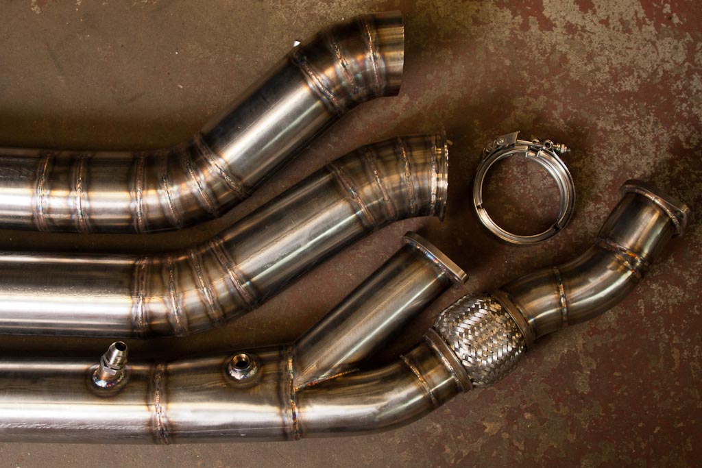
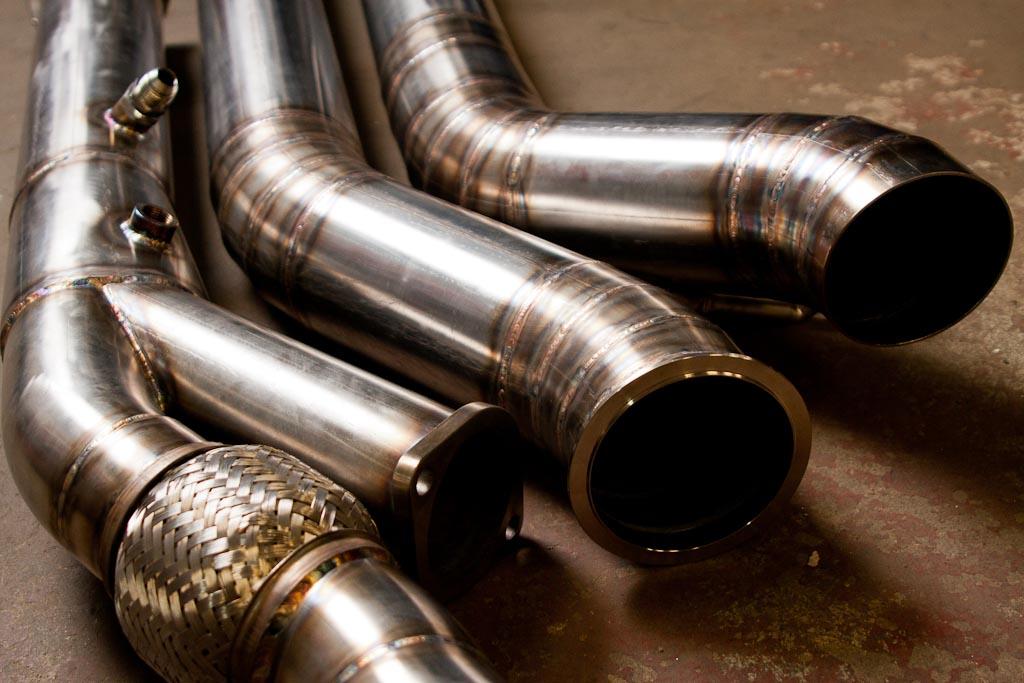
We received a box with all the pieces required to build TIG weld this stainless steel midpipe. When you have a customer that provides parts with excellent fit-up it makes welding a breeze! All the pieces had index marks and were numbered so we knew what order to weld these pieces up and how they were orientated to each other. This midpipe is backpurged and TIG welded, we also used some Kapton tape to reduce wasting backpurge gas and to ensure no air was being brought inside the tubing.
We used some scrap rectangular tubing as spacers to keep everything nice and straight during the tacking process.
The midpipe is now ready for welding. Kapton tape is the best for sealing up tacked joints, it leaves no residue when removed, can withstand 400°C and makes anything stainless look like something from NASA. This allows for the use of less argon during backpurging which ultimately saves the customer money. Here we have all the joints taped up, and the argon is flowing inside the tubing to provide an inert atmosphere to protect the inside of the weld. After a few minutes we begin welding.
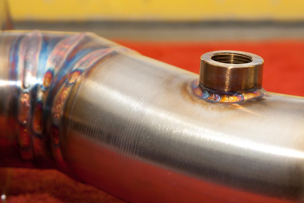
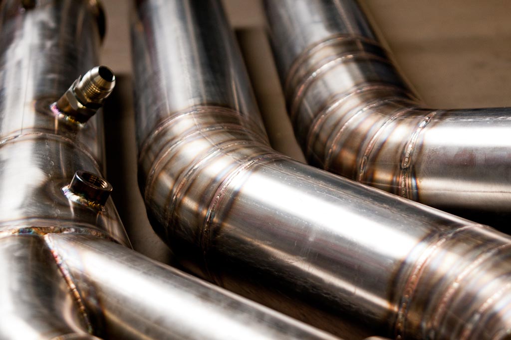
Some of the first beads. The welds look good on the outside, but also look just as good on the inside.
Welding in the O2 bung.
The stainless steel midpipe is completely done and ready to be packaged and sent back to our customer. Anything with a nice surface finish we wrap up with extra care in order to reduce the chances of any stray scratches. Repurposing towels works great for protecting the metalwork while in transit to the customer (along with shredded paper filler material).
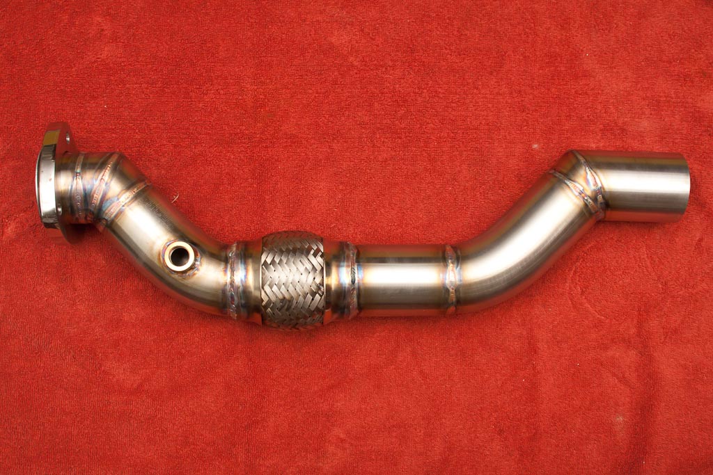
2.5″ dual exhaust construction
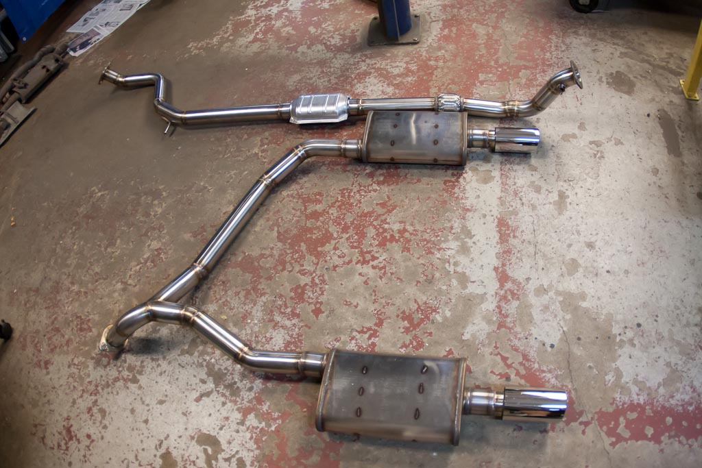
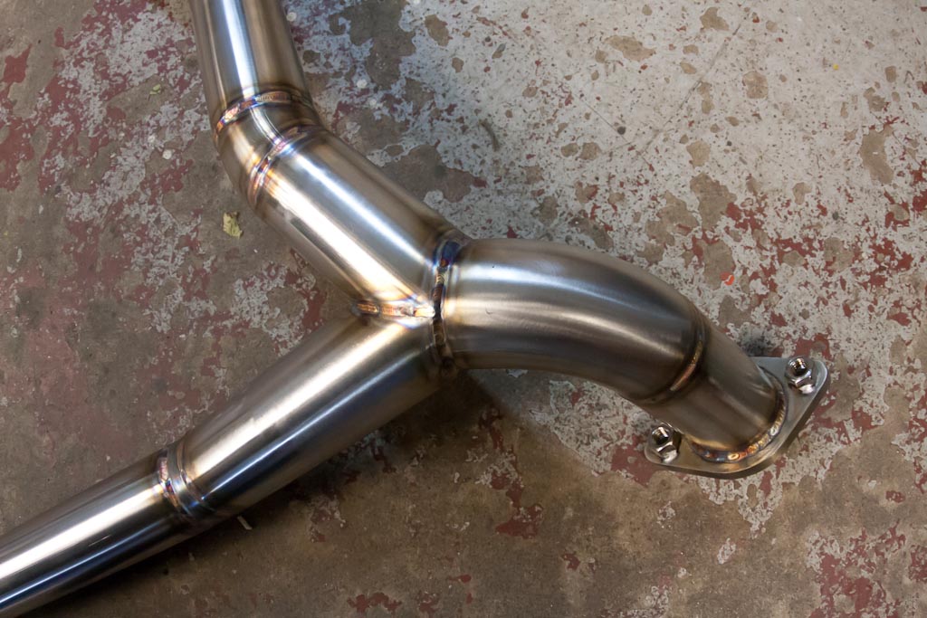
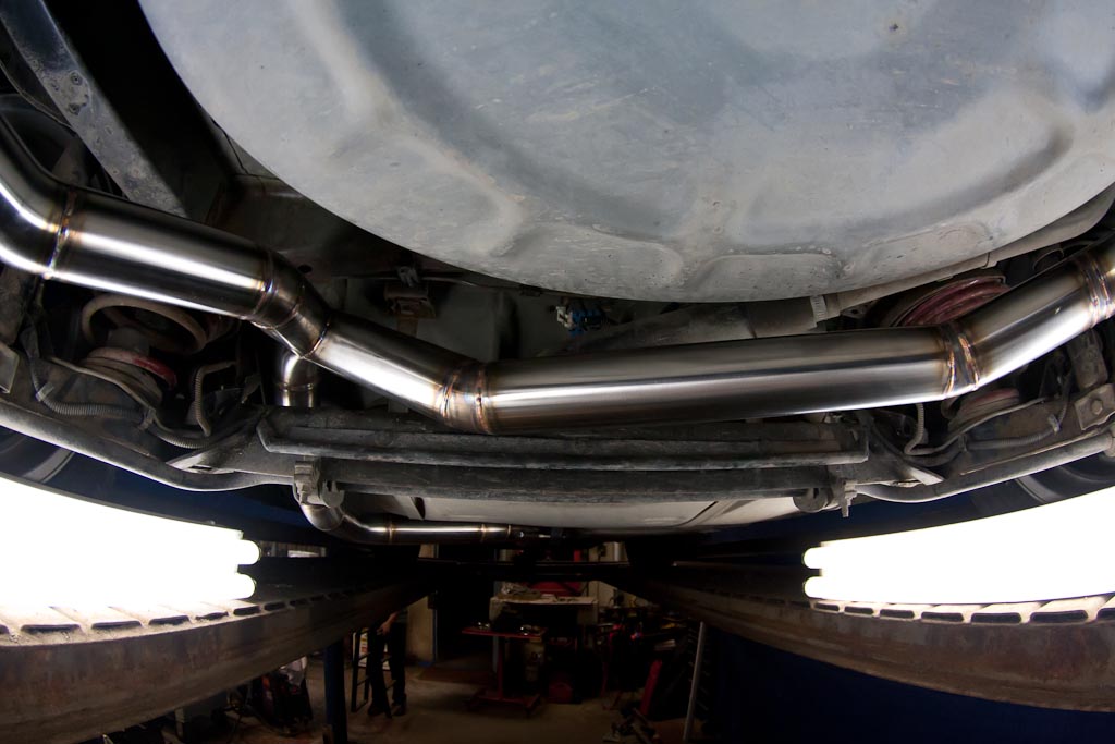
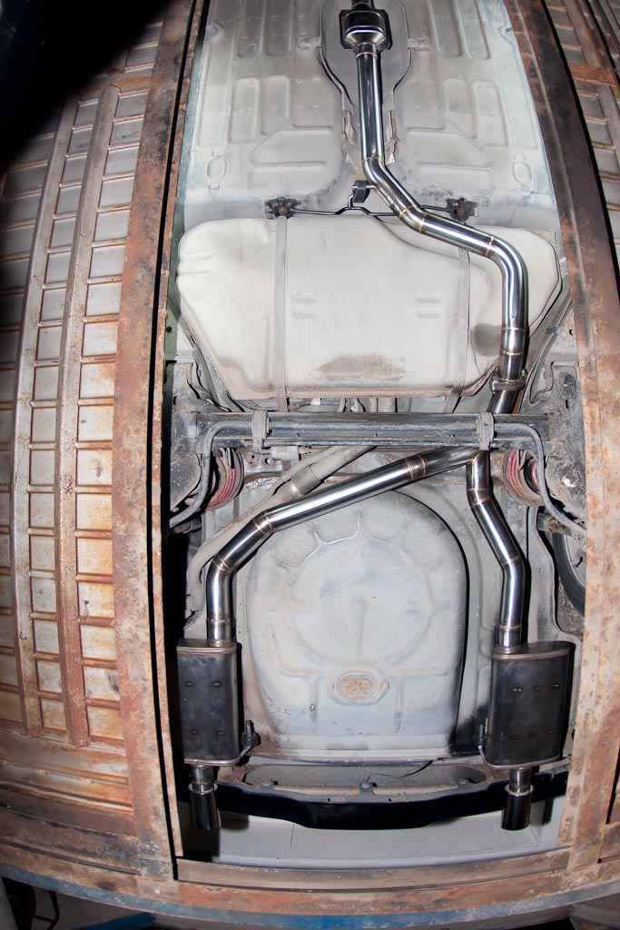
Here we’re working on a super clean Pontiac Sunbird building a stainless steel 2.5″ dual exhaust system that splits over the rear axle. This 2.5″ dual exhaust system is 100% TIG welded and backpurged to allow for the highest quality welds.
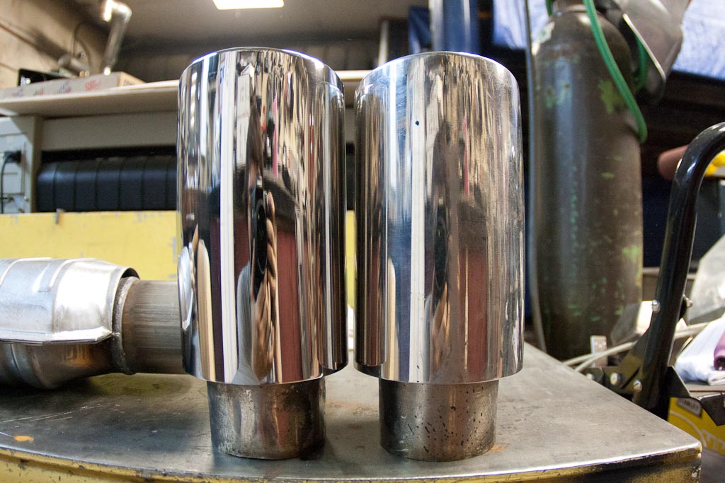
The customer wanted to reuse the exhaust tips so one down one to go, cleaning up and polishing the old tips that have their share of scratches and road grime. We used the Baldor polisher with a sisal wheel with black emery compound for a rough cut, then a spiral sewn wheel with brown tripoli compound for a final cut. Take a look at our polishing services offered here for more info.
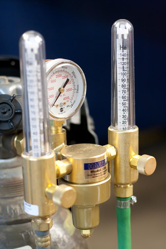
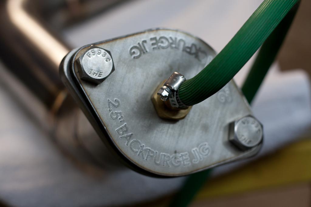
Here’s the backpurge setup running, one flow meter (grey hose) is for the TIG the other (green hose) is for backpurging the inside of the exhaust prior to welding.
Here’s the Mint Design backpurge jig knocked off the CNC table. It can bolt up to begin backpurging any 2.5″ exhaust system, or at least systems with the same bolt pattern. We’ll be cutting a set of flanges to allow backpurge from 2″ up to 4″ exhaust flanges.
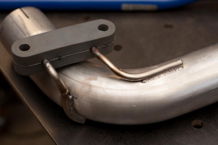
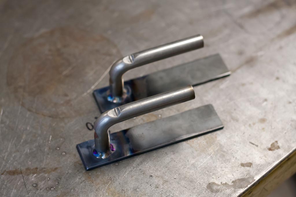
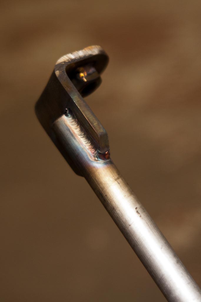
The old muffler hangers were not the best, we ended up removing them off the car, so here are the new ones to be welded to the car. They are solid 1/2″ 304SS rod welded to a steel plate with 309 filler. the 309 filler allows for stainless steel to be welded to mild steel. The purpose for the mild steel base flange is that it’ll be MIG welded back onto the steel body of the car.
Here’s the entire 2.5″ dual exhaust system completed.
R32 Skyline Ø4″ exhaust system
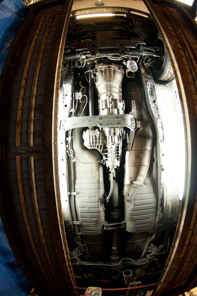
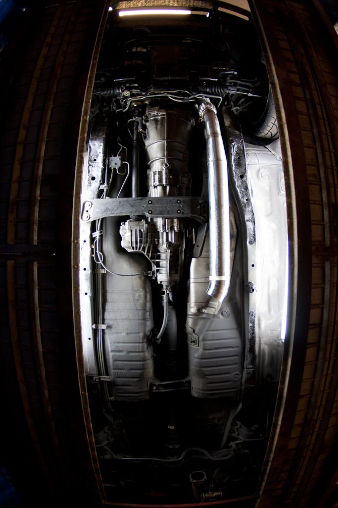
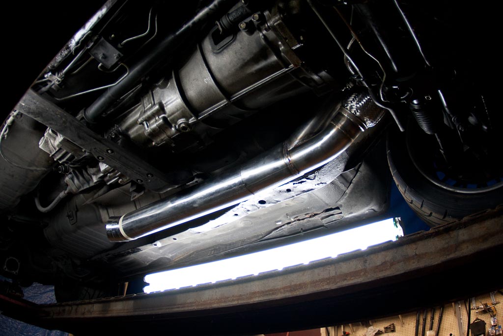
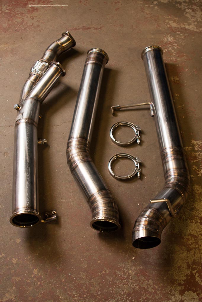
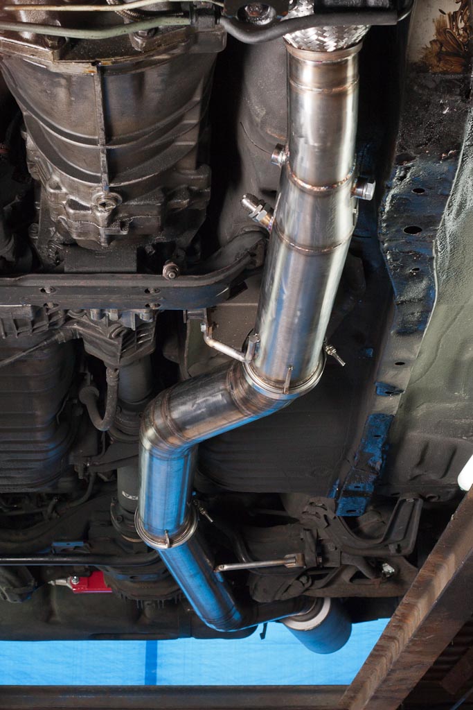
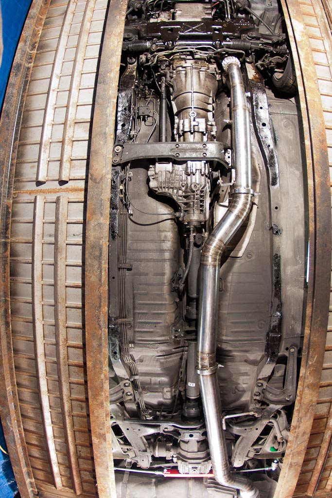
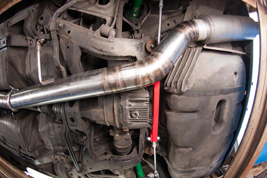
What’s not to love about twin turbo and the AWD drivetrain of the Nissan R32 Skyline? Here we are building a 304 stainless steel exhaust system that will allow this R32 Skyline to exhale with ease. Here are some progress shots of a twin 3″ merging to a 4″ exhaust system.
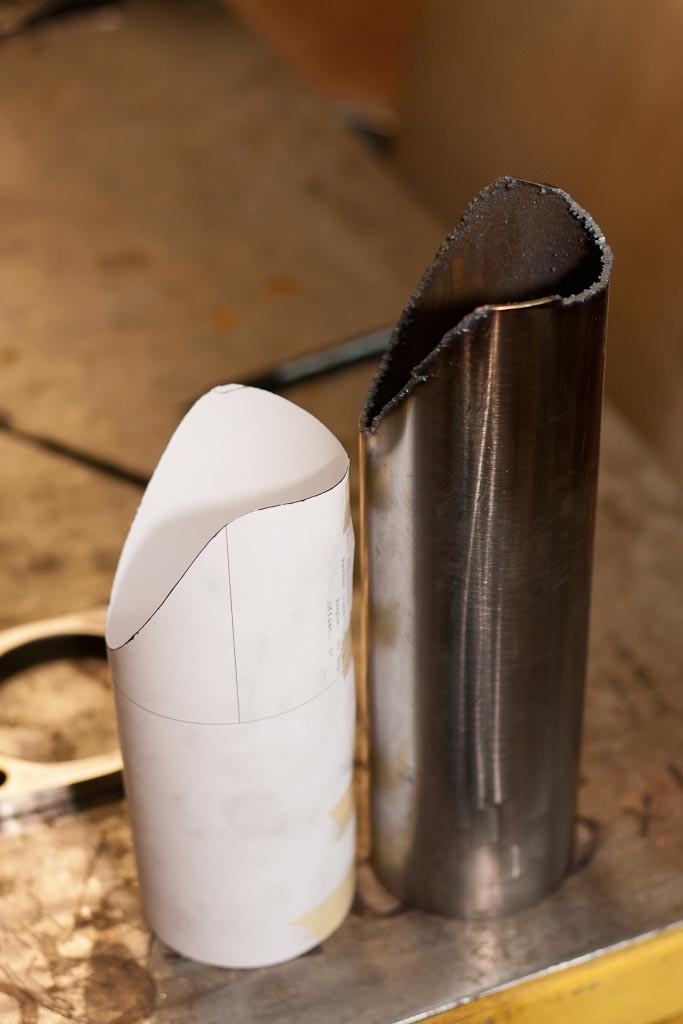
Using a paper template to coping the stainless steel tubing with the plasma cutter.
And after about 35′ of welding this is what is left (sans muffler).
Might not look like much, but the bracket was cut on the CNC table. Quicker and easier than doing it by hand.
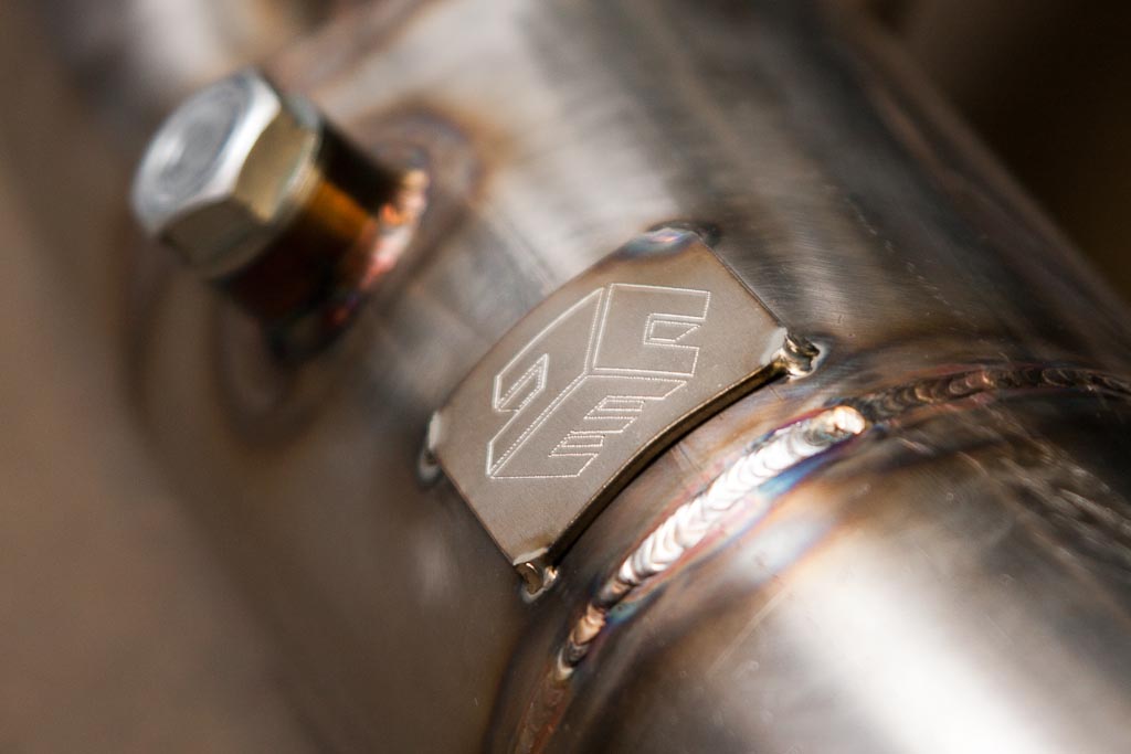
The seal of approval (ACE Engineering’s previous logo).
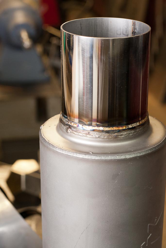
Lightly polished SS tip welded onto the muffler
All done and mounted. Notice the subtle V-band guards cut out on the CNC table. Due to the nature of this exhaust system it sits quite low, so to mitigate any damage from speed bumps or anything snagging the V-band clamps, the guards prevent it from getting snagged and cause expensive damage.

